WHY HAVE A CONNECTOR
Connectors are used to join two fibres together, or to connect a fibre to a piece of equipment (such as the end communications transmission equipment or a piece of test equipment). Connectors are used in preference to a splice where the need is for a join to be non-permanent with easy connection/disconnection.
There are two main ways of describing optical connectors - by the 'family' or type of connector, and by the type of end finish that they have.
CONNECTOR TYPES
All common optical connectors share the same base construction philosophy in that they consist of a mechanical housing through which a fibre passes to a polished end. The protruding connector part that houses the fibre is a called a ferrule and this normally includes a spring that provides axial pressure when two connectors are mated. This means that the end face pressure is set by the spring rather than how tightly the end user tightens the coupling nut.
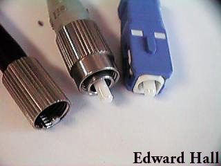
Three common connector types used in Telecom applications are shown. From left to right these are 'D4', 'FC', and 'SC'. The center ferrules can be seen protruding from the main connector body. The centre of the ferrule has a small hollow bore in which the fibre is cemented in place. The end is then polished until the final end quality is achieved. The D4 and FC both use threaded coupling nuts, while the SC uses a positive locking push fit.
A common connector used in long haul links and test equipment is the FC/PC. Typical insertion losses for this type of connector is 0.27dB, with a durability of around 1000 connections / disconnection's.
Common connector families in use are FC, ST, SMA, D4, Din, Biconic, Mini-BNC, and SC.
CONNECTOR END FINISHES
The end of the connector ferrule can have a number of possible finishes depending on the age of connector or its application.
FLAT CONNECTORS were usually slightly concave which prevented contact in the central core area. Note flat connectors are still used on many multimode installations and are easy to field polish.
PC CONECTORS have the convex end face so that the physical contact occurred. SUPER PC CONNECTORS and ULTRA PC CONNECTORS were developed to further reduce the reflection. Generally the ferrule radius was reduced from that of the standard PC finish, and a softer material used. The softer ferrule material resulted in a reduction in the amount of fibre undercut that was occurring in the standard PC connector and this gave an improvement in performance. Better polishing techniques reduce the amount of stress that occurred at the end face. The ultra PC connectors are more applicable in high data rate systems at 2.4Gb/s and above, such as a SDH STM16 system. Some problems have been reported where standard PC finished connectors have been used near to transmitters on high data rate systems and this has resulted in problems getting the system error free when the connector is disturbed for activities such as maintenance.
ANGLED CONNECTORS represent a newer connector technology. These can be polished to any of the finishes above however the end is also angled so that any reflection that does occur leaves the core and is not transmitted back down the fibre. Angled physical contact connectors have become common in recent years in cable TV systems where reflections result in reduce signal quality. The SC/APC is one of the most common in the cable TV application.
THROUGH ADAPTERS
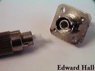
Pictured is a FC/PC connector along with its through adapter. The center alignment sleeve can be seen in the adapter. This sleeve provides the means for the accurate alignment of the ferrules - essential if a low insertion loss is to be achieved.
Also visible is the key on the connector along with the matching keyway on the adapter. The two holes on the square flange are for mounting the adapter.
CONNECTOR CLEANING
With the core of a single mode fibre being only 9 to 10 microns in size a lot of air-borne particles can easily cover much if not all of the core area on the end face of the connector. In addition connector damage can occur if foreign particles are caught in the end face area of mated connectors. The solution is to make sure that cleaning of connectors is completed by all staff handling them, and that 'good housekeeping' practices are employed such as always installing the protective caps and never allowing any object other than the approved cleaners to contact the end face.
Connector cleaning is simply completed by wiping the connector ferrule and end face with some isopropyl alcohol and a lint free tissue.
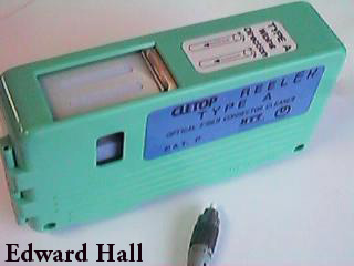
Another option for connector cleaning is the cassette type cleaners. These use a dry tape system where the tape is advanced every time the cassette is opened ensuring the a clean section of tape is used each time. It is my view that the cassette devices are not technically as good as careful use of alcohol and lint free tissue but the practicalities of field conditions is such that the use of lint free tissues is difficult. The result is often a preference for cassette cleaners in the field.
Through adapters are primarily kept clean by always cleaning the connectors prior to insertion. A method of cleaning through adapters is the careful use of a can of compressed gas. An alternative is a pipe cleaner moistened with isopropyl alcohol. Remember that most pipe cleaners have a steel wire center and the end will damage any connectors if it is inserted into a adapter with a connector still inserted in the other side.
Return to Optical Fibre Technology Main Page
Created 1 March 1996: Last modified: 24 April 1998.
Rev: 4
Copyright ©1997, 1998 Edward Hall. All rights reserved.
This material may only be downloaded for educational purposes. Printed copies may be made provided they are withou modification and are complete with source and copyright information. Please promote the future of Internet publishing by respecting the copyright of items on the net.