| INTRODUCTION TO THE OTDR
One of the more complex test instruments used for general field testing of fibre optic cable systems is the Optical Time Domain Reflectometer (OTDR). OTDR's produce a graphical representation of optical changes or 'events' on a fibre. An event could be a splice, optical connector, a bend, a break, or just normal backscattered light from the fibre itself.
|
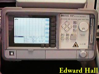
| The HP 8147 OTDR is typical of many modern high quality OTDR's. It is a software controlled machine running in a microsoft Windows95 operating system.
The front panel consists of a display area (in this case a large colour LCD), a control panel with buttons for major functions, plus the built in printer (behind the hinged flap next to the power switch at the bottom), plus the optical connector (behind the hinged flap at the bottom right hand side).
| 
|
| OTDR TRACES
The OTDR sends out a pulse of light and provides a 'trace' against time of the returned light. The OTDR is calibrated such that it uses the speed of light in the fibre to convert its time axis to distance (miles or kilometers). The vertical axis is calibrated in dB. The following is the trace as would be displayed on a HP8147 OTDR.
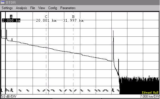
The vertical axis is calibrated at 5dB/division and the horizontal axis at 7dB/division. The markers are used to take distance measurements as shown, and are also used for more advanced measurements. The 'event bar' at the bottom identifies all the locations on the trace that an event is seen by the OTDR. A number of different types of events can be seen on trace.
|
| TYPES OF EVENTS |
| The 'fibre' itself is produced by light that is backscattered as the pulse from the OTDR travels along the fibre. This backscatter is produced by (mainly) impurities in the fibres material. The backscatter slopes down to the right due to the pulse of light being attenuated as it travels away from the OTDR.
| 
|
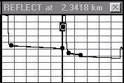
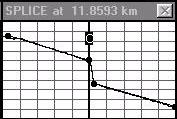
| A reflection combined with a loss (as shown at the point of the bold vertical bar labeled C) is usually either a mechanical splice or a connector, but could also be a crack in the fibre. As the locations of connectors and mechanical splices is normally known the identification of the type of event should be easy.
| 
|
| A point loss which has no reflection is usually either a fusion splice or a bend. Again splice locations should be known so differentiating between splices and bends is normally easy. Note that if a good splice is testing really bad it can mean that their is a bend nearby and the OTDR is not able to split the two close together events.
| 
|
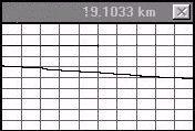
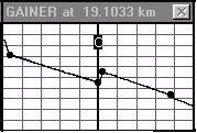
| Here the level of backscatter before and after a fusion splice shows a upwards trend, usually called a 'gainer splice' or simply a 'gain'. This is not due to the splice having an actual gain but is instead a result of the second fibre have a higher backscatter. If the OTDR was placed at the far end of the fibre (so that we view from the higher backscatter fibre to the lower one) then we would see a large loss through the same splice. The actual splice loss is the average of the splice loss measured in both directions.
| 
|
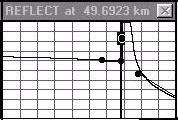
| The end of this fibre shows a strong reflection as it is terminated in a polished connector. If the end was shattered or immersed in water (as can happen in a broken cable situation) then there may be a smaller reflection or no reflection at all.
| 
|
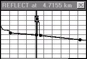
| This is a reflective feature that has no loss. This is due to a double reflection, normally where light reflected back towards the OTDR is reflected back into the fibre from the OTDR's front connector, only to be re-reflected back to the OTDR by a reflective event. 'Ghostbusting' techniques are used by experienced technicians to get rid of ghosts.
| 
|
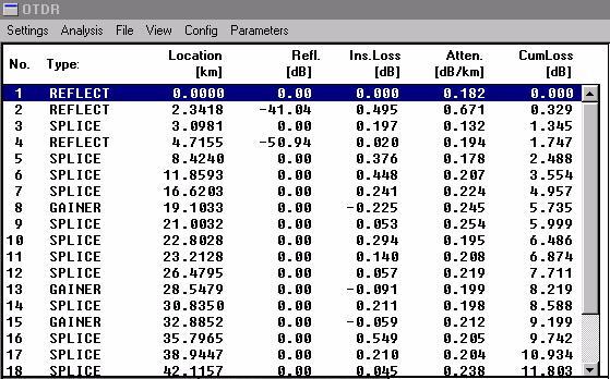
| EVENT TABLE |
| Nearly all modern OTDR's include the ability to 'scan' the trace and produce an event table. This event table contains information on the type, size, and location of all events that the OTDR is able to locate.
|
| CONNECTOR CARE |
| The front connector of the OTDR needs to be treated with care like all connectors (see the tutorial on optical connectors).
Older OTDR's used standard through adapters which the fibre under test is plugged into. Should the connector within the OTDR get dirty then the OTDR needed to be dismantled in order to get access to clean the internal pigtail.
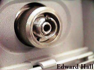
Modern OTDR's use an adapter as shown in the picture
| 
|
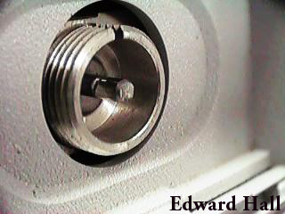
This modern OTDR has a specialised front connector where the adapter can be used leaving exposed a ferrule that can have its end face cleaned without the need to dismantle the OTDR further.
Note while cleaning is easier it is harder for the user to replace the front connector if it should get damaged under use.
| 
|
| |
| This page is still under construction. It will be completed as time allows.
|
Return to Optical Fibre Technology Main Page
Last modified: 13 March 1998.
Copyright ©1997, 1998 Edward Hall. All rights reserved.
This material may only be downloaded for educational purposes. Printed copies may be made provided they are done so without modification and complete with source and copyright information. Please promote the future of Internet publishing by respecting the copyright of items on the net.
|